So, what exactly is a SubVI? It is a VI that is placed on the block digram of a higher level VI. It allows you to write modules of code that you can wire into your diagrams later. The icon is what the SubVI will look like on another VIs block diagram. The connector pane allows you to assign terminals on the icon to front panel controls and indicators for the purpose of wiring values into and out of a SubVI.
The SubVI interface (icon and connector pane) is not as immediately obvious as the front panel and block diagram when a VI is opened. It is accessible from the upper right hand corner of the front panel window:
By default the icon is displayed.
By right clicking on the icon you will see a pop-up menu. You can see there are options for setting properties of the current VI, Editing the Icon, and Showing the connector pane. In this menu you should select Show Connector:

Upon doing so, the icon image will change to a layout of the connector pane:

By clicking on the regions in the connector pane with the wiring tool, and then clicking on front panel objects, the VI becomes a usable SubVI. There are no requirements on how many or how few of the front panel objects should be wired. It is up to you if the value is needed for the program to function properly. If a front panel object is not connected to the connector pane, then the default value will likely be used when the VI is called from another VI as a SubVI.
Now let's create a SubVI to make this clear.
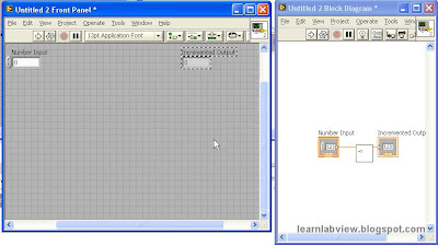
First, create a VI. In this case, a simple one shot VI that increments a value will suffice. This is similar to the first example in this tutorial.
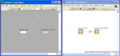
Next you will need the connector pane visible and the wiring tool selected. The wiring tool is always selected when you use the right click menu on the icon to choose "Show Connector". Therefore, if the connector pane is visible but the wiring tool is not selected, go back to the Icon, then back to the Connector again. (i.e. right click -> "Show Icon" -> right click -> "Show Connector") This is a trick to get to the wiring tool with the connector pane quickly.
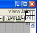
Left click with the wiring tool on the upper left terminal of the connector pane and it will turn black:
 Then left click on the input control on the front panel GUI:
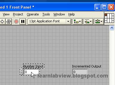 Note that the terminal turns an orange/grey highlighted color, indicating that the link is established between that terminal and the "Number Input" control. When you click off of the Number Input control, the terminal is shown as being linked but not selected:
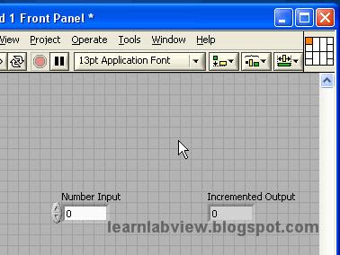
Now, follow the same steps to connect the indicator terminal and it should look like this:
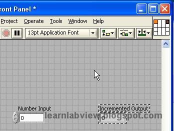 Now that the connector pane is wired for this VI, it is a usable SubVI. However, to make it easily identifiable in the block diagrams of VIs that call it, you should give it a custom icon. This is not necessary, but a brief summary of the steps follow:
Use the right click menu on the Icon or Connector Pane to select "Edit Icon". The following utility appears:
This program operates more or less like a rudimentary paint program. I drew the following simple icon for this example:
Hit OK, and the VI now uses the new icon.
Note that the icon appears at the upper right of the VI windows:
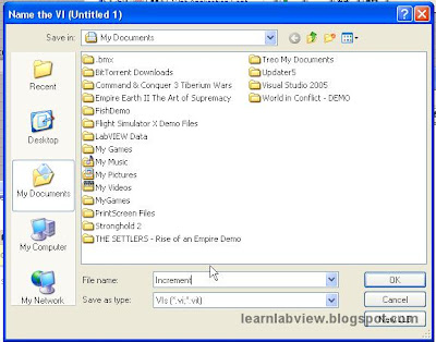
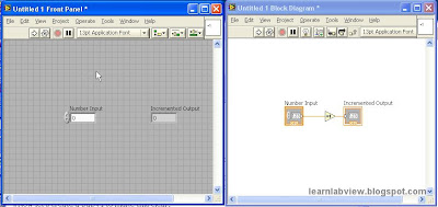 Now, before LabView can use this Untitled VI as a SubVI, it needs to be saved. It should be given a reasonable name. Select File->Save As, then navigate to a folder where you would like to save this VI. I named it "Increment". The .VI extension is automatically added by LabView.
Now to see this newly saved SubVI in action.
Start a new blank VI and open the Block Diagram menu:
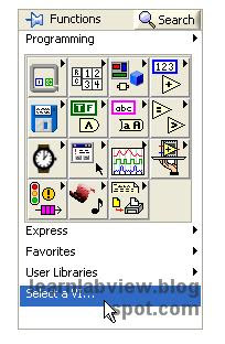 Hit "Select a VI" then select the SubVI from the location where you saved it.
Immediately you will be holding something that looks like the Icon of the SubVI to be placed on the block diagram of this new VI:
 Once it is placed, you will find that by hovering over the terminals that were attached on the connector pane, you will find wiring locations that correspond to the front panel objects of the original VI. For example, hovering over the upper left terminal shows that there is a wiring site for "Number Input".
Whatever you wire into that terminal on this block diagram will essentially run the original VIs block diagram with that value. This is all represented just by this icon you have placed. That is the power of the SubVI. For programmers, you will recognize this is the same as a function, module, subroutine, etc.. SubVI is the LabView name for this.
Below is an example of what it might look like once the SubVI is wired into this new VI:
Note that this new VI has the default Icon and if you go to its connector pane, it is empty. You could set this VI up as another SubVI.


No comments:
Post a Comment